A friend introduced me to microcontrollers a while back, and I was instantly fascinated. After learning the basics, like blinking LEDs and controlling motors, I was eager to tackle more advanced projects. As I researched, I noticed that many intriguing projects involve an IMU (Inertial Measurement Unit) sensor. That's when I decided to dive into working with the MPU-6050 sensor—a 6-axis gyroscope and accelerometer module. The MPU-6050 is highly popular among hobbyists and professionals, and I chose to learn how to interface it with an STM32 microcontroller.
This article is the first part of a two-part series documenting my attempt to interface the MPU-6050 with an STM32 microcontroller. In this part, I will develop a driver for the MPU-6050 to read accelerometer and gyroscope data.
**Note: This article does not go into details on how to start a STM32 project. Please refer to ST wiki page if you want to get started on STM32 microcontroller.
Before we start writing the driver, we need to set up the hardware connections between the STM32 microcontroller and the MPU-6050 sensor. The MPU-6050 communicates with the STM32 microcontroller using the I2C protocol. The I2C protocol requires two lines: SDA (Serial Data Line) and SCL (Serial Clock Line). The SDA line is used to transfer data between the microcontroller and the sensor, while the SCL line is used to synchronize the data transfer.
To connect the MPU-6050 to the STM32 microcontroller, follow these steps:
After connecting the MPU-6050 to the STM32 microcontroller, we can start writing the driver to read accelerometer and gyroscope data from the sensor.
With the hardware and software set up, the next step is to develop a driver to interface with the MPU-6050 sensor. The driver will handle all communication between the STM32 microcontroller and the MPU-6050 over I2C, allowing us to read accelerometer and gyroscope data.
To properly initialize and configure the MPU-6050, specific registers within the sensor must be set. These registers control various settings such as the sensitivity of the accelerometer and gyroscope, power management, and data output format.
First, we need to obtain the I2C address of the MPU-6050 sensor (MPU-6050 Product Specification, section 6.4). The default I2C address of the MPU-6050 is 0x68. However, the address can be changed by grounding the AD0 pin of the sensor. If the AD0 pin is grounded, the I2C address becomes 0x69. In this project, I will use the default address of 0x68.


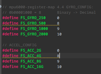
Then, we can define the gyroscope and accelerometer sensitivity ranges (MPU-6050 Register Map and Descriptions section 4.4 and 4.5). The sensitivity ranges determine the resolution of the sensor data.

Finally, we also need to define the power management register, gyroscope configuration register, and accelerometer configuration register of the MPU-6050 (MPU-6050 Register Map and Descriptions section 4.4, 4.5, and 4.28). The power management settings control the sleep mode, clock source, and temperature sensor of the sensor.

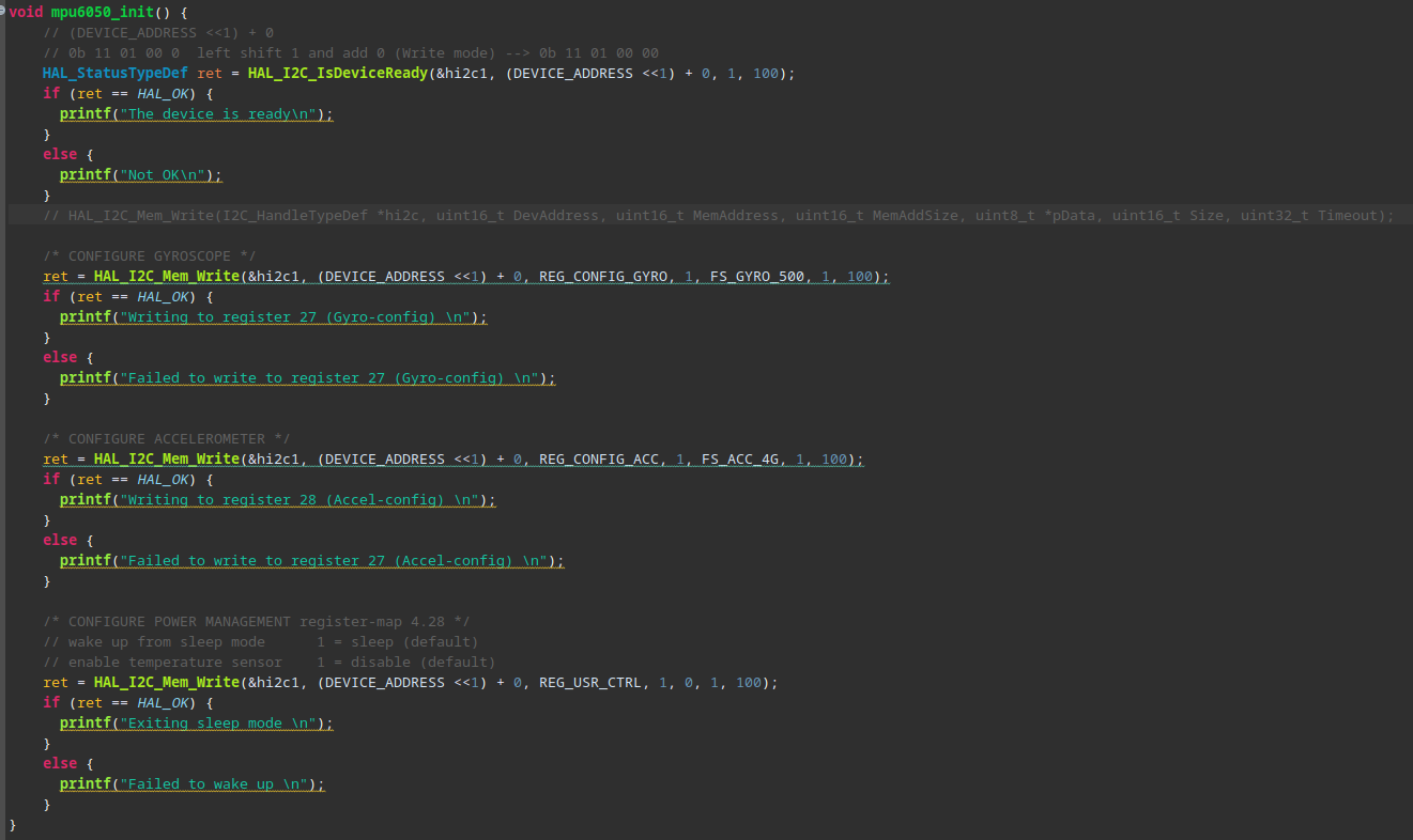
After defining the necessary registers, we can start writing the initialization function for the MPU-6050 sensor mpu6050_init(). The initialization function will configure the I2C communication, set the sensor registers, and prepare the sensor for data reading.

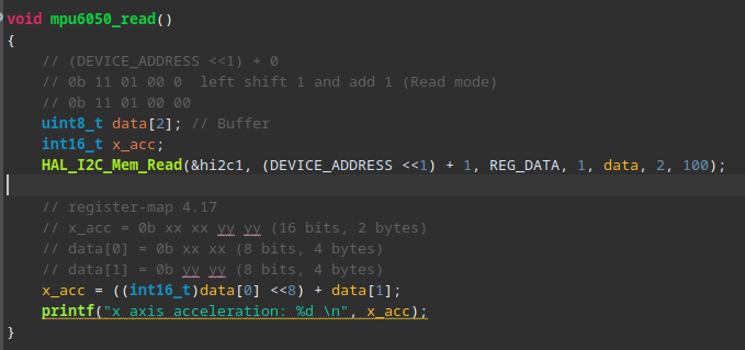
Once the sensor is initialized, we can read accelerometer and gyroscope data from the MPU-6050 sensor. The data is stored in specific registers within the sensor, and we can read these registers to obtain the sensor data.

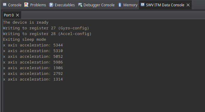
After developing the MPU-6050 driver, we can now read accelerometer and gyroscope data from the sensor through the IDE SWV (Serial Wire Viewer).

In this article, we explored the process of interfacing the MPU-6050 sensor with an STM32 microcontroller. We discussed the hardware connections between the sensor and the microcontroller, the development of an MPU-6050 driver to read accelerometer and gyroscope data, and the initialization and configuration of the sensor registers.
Developing the MPU-6050 driver is the first step in working with the sensor. In the next part of this series, we will focus on processing the sensor data and visualizing it on a computer using a serial communication protocol.